
Diodes Incorporated BSS84-7
- Part Number:
- BSS84-7
- Manufacturer:
- Diodes Incorporated
- Ventron No:
- 2492129-BSS84-7
- Description:
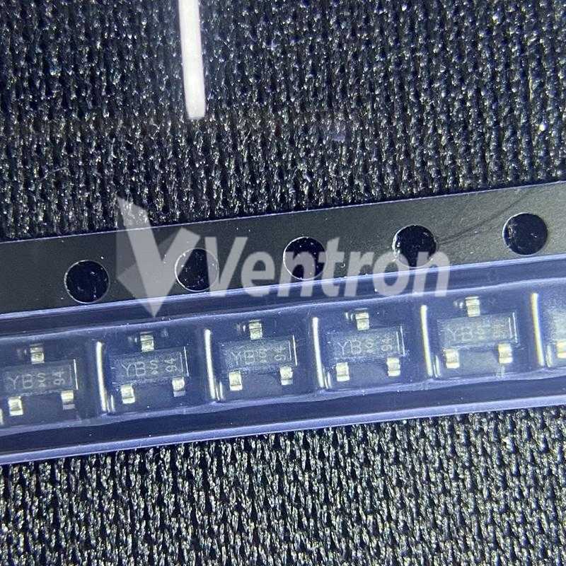
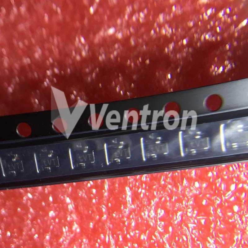
- MOSFET P-CH 50V 130MA SOT23-3
- ECAD Model:
-
- Datasheet:
- BSS84-7


Diodes Incorporated BSS84-7 technical specifications, attributes, parameters and parts with similar specifications to Diodes Incorporated BSS84-7.
- Contact PlatingLead, Tin
- MountSurface Mount
- Mounting TypeSurface Mount
- Package / CaseTO-236-3, SC-59, SOT-23-3
- Number of Pins3
- Weight7.994566mg
- Transistor Element MaterialSILICON
- Operating Temperature-55°C~150°C TJ
- PackagingTape & Reel (TR)
- Published2003
- JESD-609 Codee3
- Pbfree Codeyes
- Part StatusDiscontinued
- Moisture Sensitivity Level (MSL)1 (Unlimited)
- Number of Terminations3
- ECCN CodeEAR99
- Terminal FinishMatte Tin (Sn)
- Additional FeatureHIGH RELIABILITY, LOW THRESHOLD
- SubcategoryOther Transistors
- Voltage - Rated DC-50V
- TechnologyMOSFET (Metal Oxide)
- Terminal PositionDUAL
- Terminal FormGULL WING
- Peak Reflow Temperature (Cel)260
- Current Rating-130mA
- Time@Peak Reflow Temperature-Max (s)40
- Pin Count3
- Qualification StatusNot Qualified
- Number of Elements1
- Number of Channels1
- Power Dissipation-Max300mW Ta
- Element ConfigurationSingle
- Operating ModeENHANCEMENT MODE
- Power Dissipation300mW
- Turn On Delay Time10 ns
- FET TypeP-Channel
- Transistor ApplicationSWITCHING
- Rds On (Max) @ Id, Vgs10 Ω @ 100mA, 5V
- Vgs(th) (Max) @ Id2V @ 1mA
- Input Capacitance (Ciss) (Max) @ Vds45pF @ 25V
- Current - Continuous Drain (Id) @ 25°C130mA Ta
- Drain to Source Voltage (Vdss)50V
- Drive Voltage (Max Rds On,Min Rds On)5V
- Vgs (Max)±20V
- Turn-Off Delay Time18 ns
- Continuous Drain Current (ID)130mA
- Gate to Source Voltage (Vgs)20V
- Height1mm
- Length2.9mm
- Width1.3mm
- REACH SVHCNo SVHC
- RoHS StatusNon-RoHS Compliant
- Lead FreeContains Lead
BSS84-7 Overview
Op amps with either input grounded have a fixed input capacitance parameter, CI, and this device has a 45pF @ 25V maximal input capacitance.Devices can conduct a maximum continuous current of 3 amps in the drain area, so the continuous drain current (ID) for this device is 130mA amps.It is [18 ns] because it takes time to charge the input capacitance of the device before drain current conduction can begin.A turn-on delay time of 10 ns indicates the time it takes for the input capacitance of the device to charge before drain current conduction starts.Generally, the gate-source voltage (VGS) of a FET transistor is the voltage across its gate-source terminal, which is 20V.To operate this transistor, you will need a 50V drain to source voltage (Vdss).A device like this reduces its overall power consumption when it uses drive voltage (5V).
BSS84-7 Features
a continuous drain current (ID) of 130mA
the turn-off delay time is 18 ns
a 50V drain to source voltage (Vdss)
BSS84-7 Applications
There are a lot of Diodes Incorporated
BSS84-7 applications of single MOSFETs transistors.
Synchronous Rectification for ATX 1 Server I Telecom PSU
Motor drives and Uninterruptible Power Supplies
Micro Solar Inverter
DC/DC converters
Power Tools
Motor Drives and Uninterruptible Power Supples
Synchronous Rectification
Battery Protection Circuit
Telecom 1 Sever Power Supplies
Industrial Power Supplies
BSS84-7 More Descriptions
Trans MOSFET P-CH 50V 0.13A 3-Pin SOT-23 T/R
MOSFET P-CH 50V 130MA SOT23-3
Transistor - FET P-Channel -50V 250mW
OEMs, CMs ONLY (NO BROKERS)
MOSFET P-CH 50V 130MA SOT23-3
Transistor - FET P-Channel -50V 250mW
OEMs, CMs ONLY (NO BROKERS)
Popular Search Part Number
Related Keywords
Search Tags
Latest News
-
17 November 2023
MSP430 Microcontroller Features, Development, MSP430 vs 89C51 and Applications
Ⅰ. What is a microcontroller?Ⅱ. Overview of MSP430 microcontrollerⅢ. Features of MSP430Ⅳ. Development of MSP430 microcontrollerⅤ. Main components of MSP430 microcontrollerⅥ. What are the advantages and disadvantages of... -
20 November 2023
What is W25Q128JVSIQ Serial Flash Memory?
Ⅰ. W25Q128JVSIQ overviewⅡ. Manufacturer of W25Q128JVSIQⅢ. Symbol, footprint and pin configuration of W25Q128JVSIQⅣ. Features of W25Q128JVSIQⅤ. Working principle of W25Q128JVSIQⅥ. Technical parameters of W25Q128JVSIQⅦ. Advantages and disadvantages of... -
20 November 2023
Comparing the DHT11 and DHT22 Temperature and Humidity Sensor
Ⅰ. What is a temperature sensor?Ⅱ. DHT11 vs DHT22: OverviewⅢ. DHT11 vs DHT22: Symbol and footprintⅣ. DHT11 vs DHT22: FeaturesⅤ. DHT11 vs DHT22: Pin configurationⅥ. DHT11 vs DHT22:... -
21 November 2023
MCP2551 CAN Transceiver Features, Working Principle, MCP2551 vs TJA1050
Ⅰ. Overview of MCP2551 transceiverⅡ. Manufacturer of MCP2551 transceiverⅢ. Features of MCP2551 transceiverⅣ. Working principle of MCP2551 transceiverⅤ. Block diagram of MCP2551 transceiverⅥ. What is the difference between...

Help you to save your cost and time.
Reliable package for your goods.
Fast Reliable Delivery to save time.
Quality premium after-sale service.