Maxim Integrated MAX14724EWP T
- Part Number:
- MAX14724EWP T
- Manufacturer:
- Maxim Integrated
- Ventron No:
- 3829122-MAX14724EWP T
- Description:
- IC MUX 8:4 3OHM 20WLP
- ECAD Model:
-
- Datasheet:
- MAX14724EWP T
Maxim Integrated MAX14724EWP T technical specifications, attributes, parameters and parts with similar specifications to Maxim Integrated MAX14724EWP T.
- Factory Lead Time6 Weeks
- Mounting TypeSurface Mount
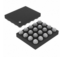
- Package / Case20-WFBGA, WLBGA
- Operating Temperature-40°C~85°C TA
- PackagingTape & Reel (TR)
- Published2015
- Part StatusActive
- Moisture Sensitivity Level (MSL)1 (Unlimited)
- Resistance3Ohm
- Peak Reflow Temperature (Cel)NOT SPECIFIED
- Reflow Temperature-Max (s)NOT SPECIFIED
- Base Part NumberMAX14724
- Number of Circuits1
- Voltage - Supply, Single/Dual (±)1.6V~5.5V ±5V
- Logic IC TypeMULTIPLEXER
- 3db Bandwidth50MHz
- On-State Resistance (Max)3Ohm
- Multiplexer/Demultiplexer Circuit8:4
- Current - Leakage (IS(off)) (Max)250nA
- Channel Capacitance (CS(off), CD(off))50pF 85pF
- Switch Time (Ton, Toff) (Max)2μs, 600ns (Typ)
- Charge Injection-15pC
- Channel-to-Channel Matching (ΔRon)500m Ω
- Crosstalk-65dB @ 1MHz
- RoHS StatusROHS3 Compliant
MAX14724EWP T Overview
This product features a surface mount mounting type and a 20-WFBGA, WLBGA package/case, making it suitable for various applications. It is conveniently packaged in Tape & Reel (TR) format for easy handling and storage. With a peak reflow temperature of NOT SPECIFIED, it offers flexibility and reliability in different operating environments. It is designed with 1 circuit and has a maximum on-state resistance of 3Ohm, ensuring efficient performance. The multiplexer/demultiplexer circuit is 8:4, allowing for versatile signal routing. It has a fast switch time of 2μs, 600ns (Typ) and a low channel-to-channel matching of 500m Ω (ΔRon), providing precise signal control. Additionally, it offers excellent crosstalk suppression of -65dB @ 1MHz.
MAX14724EWP T Features
-3db Bandwidth: 50MHz
MAX14724EWP T Applications
There are a lot of Maxim Integrated MAX14724EWP T Analog Switches & Multiplexers ICs applications.
Channelized and Unchannelized DS3 applications
Avionics test equipment
Precision instrumentation
Transmit
65 V DACs
E1 Multiplexer
Wireless Local Loop
Audio/video switches
Relay Replacement
Fiber In The Loop (FITL)
MAX14724EWP T More Descriptions
Serial-Controlled 8:4 Matrix Switch Multiplexer
Multiplex ±2.5V Common-Mode Signals in Tiny PackageCiiva Crawler
IC MUX 8:4 3OHM 20WLP
Multiplex ±2.5V Common-Mode Signals in Tiny PackageCiiva Crawler
IC MUX 8:4 3OHM 20WLP

Popular Search Part Number
Related Keywords
Search Tags
Latest News
-
11 April 2024
A Complete Guide to IR2104 Half-Bridge Driver
Ⅰ. IR2104 descriptionⅡ. IR2104 half-bridge driver circuit characteristicsⅢ. IR2104 half-bridge driver working principleⅣ. Practical application of IR2104Ⅴ. Recommended operating conditions of IR2104Ⅵ. What are the heat dissipation measures... -
11 April 2024
74LS138 Decoder Working Principle, Application Scenarios and 7AHC138 vs 74LS138
Ⅰ. Introduction to 74LS138Ⅱ. What is the meaning of the 74LS138 naming?Ⅲ. Working principle of 74LS138Ⅳ. Example of application circuit diagram of 74LS138Ⅴ. Application scenarios of 74LS138 decoderⅥ.... -
12 April 2024
L298N DC Motor Drive Module: Features, Pinout, Usage and Application
Ⅰ. Introduction to L298NⅡ. Functional features of L298NⅢ. L298N circuit diagramⅣ. Control method of L298NⅤ. Pin diagram and functions of L298NⅥ. How to use L298N?Ⅶ. How to use... -
12 April 2024
STM32F407ZGT6: Powerful and Flexible Microcontroller
Ⅰ. Overview of STM32F407ZGT6Ⅱ. Functional features of STM32F407ZGT6Ⅲ. Absolute maximum ratings of STM32F407ZGT6Ⅳ. The role of STM32F407ZGT6Ⅴ. Application scope of STM32F407ZGT6Ⅵ. What are the debugging interfaces of STM32F407ZGT6?Ⅶ....

Help you to save your cost and time.
Reliable package for your goods.
Fast Reliable Delivery to save time.
Quality premium after-sale service.